Sunday, January 29, 2012

Fiber-Optic Performance Factors


During the course of a normal fiber installation, you must be aware of a few factors that can negatively affect performance. They are as follows:
  • Attenuation
  • Acceptance angle
  • Numerical aperture (NA)
  • Modal dispersion
  • Chromatic dispersion

Attenuation

The biggest negative factor in any fiber-optic cabling installation is attenuation, or the loss or decrease in power of a data-carrying signal (in the case of fiber, the light signal). It is measured in decibels (dB or dB/km). In real-world terms, a 3dB attenuation loss in a fiber connection is equal to about a 50 percent loss of signal. Figure 1 graphs attenuation in decibels versus percent signal loss. Notice that the relationship is exponential.

 
Figure 1: Relationship of attenuation to percent signal loss of a fiber-optic transmission
Cables that have higher attenuation typically have lower maximum supportable distances between transmitter and receiver. Attenuation negatively affects transmission speeds and distances of all cabling systems, but fiber-optic transmissions are particularly sensitive to attenuation.
Many different problems can cause attenuation of a light signal in an optical fiber, including the following:
  • Dirty fiber end-faces (accounts for 85 percent of attenuation loss issues)
  • Excessive gap between fibers in a connection
  • Improperly installed connectors leading to offsets of the fiber cores when mated
  • Impurities in the fiber
  • Excessive bending of the cable
  • Excessive stretching of the cable (note, however, that only bending causes light loss, not stretching; stretching the cable can cause the fiber to bend, causing light loss or attenuation)

Acceptance Angle

Another factor that affects the performance of a fiber-optic cabling system is the acceptance angle of the optical-fiber core. The acceptance angle (as shown in Figure 2) is the angle through which a particular (multimode) fiber can accept light as input.

 
Figure 2: An illustration of multifiber acceptance angles
The greater the acceptance angle difference between two or more signals in a multimode fiber, the greater the effect of modal dispersion. The modal-dispersion effect also has a negative effect on the total performance of a particular cable segment.

Numerical Aperture (NA)

A characteristic of fiber-optic cable that is related to the acceptance angle is the numerical aperture (NA). The NA is calculated from the refractive indexes of the core and cladding. The result of the calculation is a decimal number between 0 and 1 that reflects the ability of a particular optical fiber to accept light.
A value for NA of 0 indicates that the fiber accepts, or gathers, no light. A value of 1 for NA indicates that the fiber will accept all light it's exposed to. A higher NA value means that light can enter and exit the fiber from a wide range of angles, including severe angles that will not reflect inside the core, but be lost to refraction. A lower NA value means that light can enter and exit the fiber only at shallow angles, which helps assure the light will be properly reflected within the core. Multimode fibers typically have higher NA values than single-mode fibers. This is a reason why the less focused light from LEDs can be used to transmit over multimode fibers as opposed to the focused light of a laser that is required for single-mode fibers.

Modal Dispersion and Bandwidth

Multimode cables suffer from a unique problem known as modal dispersion, which is similar in effect to delay skew, relative to twisted-pair cabling. Modal dispersion, also known as differential mode delay (DMD), causes transmission delays in multimode fibers. Modal dispersion is the main property affecting the multimode fiber's bandwidth.
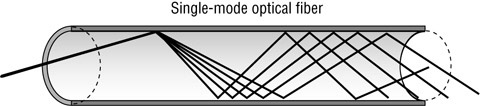
Here's how it occurs. The modes (signals) enter the multimode fiber at varying angles, so the signals will enter different portions of the optical core. In simple terms, the light travels over different paths inside the fiber and can arrive at different times as a result of different refractive indexes over the cross-sectional area of the core (as shown in Figure 3). The more severe the difference between arrival times of the modes, the more delay between the modes, and the lower the bandwidth of the fiber system.

 
Figure 3: Illustration of modal dispersion
In Figure 3, mode A will exit the fiber first because it has a shorter distance to travel inside the core than mode B. Mode A has a shorter distance to travel because its entrance angle is less severe (i.e., it's of a lower order) than that of mode B. The difference between the time that mode A exits and the time that mode B exits is the modal dispersion or DMD. Modal dispersion gets larger, or worse, as the fiber transports more modes or if there is an imperfection in the graded index refractive index profile. Multimode fiber with a 62.5 micron core carriers more modes than 50 micron fiber. As a result, 62.5 micron fiber has higher modal dispersion and lower bandwidth than 50 micron fiber. Fiber manufacturers pay careful attention to manufacturing the refractive index profiles of graded-index multimode fibers in order to reduce modal dispersion and thereby increase bandwidth. Differential mode delay is measured by fiber manufacturers and is directly related to bandwidth.

Chromatic Dispersion

The last fiber-optic performance factor is chromatic dispersion, which limits the bandwidth of certain single-mode optical fibers. Contrary to popular belief, lasers cannot emit one pure wavelength of light. Lasers emit a distribution of wavelengths with the characteristic laser wavelength in the center. (Granted, the distribution is very tight and narrow; it is a distribution, nonetheless.) These various wavelengths of light transmitted by the laser spread out in time as they travel through an optical fiber. This happens because different wavelengths of light travel at different speeds through the same media. As they travel through the fiber, the various wavelengths will spread apart (as shown in Figure 4). The wavelengths will spread farther and farther apart until they arrive at the destination at completely different times. This will cause the resulting pulse of light to be wider, less sharp, and lower in overall power. As consecutive pulses begin to overlap, the signal detection will be compromised. Multimode fiber can also have this problem, and this combined with modal dispersion lowers the bandwidth of multimode fibers compared to single-mode, which is mainly impaired only by chromatic dispersion.

 
Figure 4: Single-mode optical fiber chromatic dispersion

Wednesday, January 25, 2012

Components of a Typical Installation


Just like copper-based cabling systems, fiber-optic cabling systems have a few specialized components, including enclosures and connectors.

Fiber-Optic Enclosures

Because laser light is dangerous, the ends of every fiber-optic cable must be encased in some kind of enclosure. The enclosure not only protects humans from laser light but also protects the fiber from damage. Wall plates and patch panels are the two main types of fiber enclosures. 
When most people think about a fiber enclosure, a fiber patch panel comes to mind. It allows connections between different devices to be made and broken at the will of the network administrator. Basically, a bunch of fiber-optic cables will terminate in a patch panel. Then, short fiber-optic patch or interconnect cables are used to make connections between the various cables. Figure 1 shows an example of a fiber-optic patch panel. Note that dust caps are on all the fiber-optic ports; they prevent dust from getting into the connector and interfering with a proper connection.

 
Figure 1: An example of a fiber-optic patch panel
In addition to the standard fiber patch panels, a fiber-optic installation may have one or more fiber distribution panels, which are very similar to patch panels, in that many cables interconnect there. However, in a distribution panel (see Figure 2), the connections are more permanent. Distribution panels usually have a lock and key to prevent end users from making unauthorized changes. Generally speaking, a patch panel is found wherever fiber-optic equipment (i.e., hubs, switches, and routers) is found. Distribution panels are found wherever multifiber cables are split out into individual cables.

 
Figure 2: A sample fiber-optic distribution panel

Fiber-Optic Connectors

Fiber-optic connectors are unique in that they must make both an optical and a mechanical connection. Connectors for copper cables, like the RJ-45 type connector used on UTP, make an electrical connection between the two cables involved. However, the pins inside the connector only need to be touching to make a sufficient electrical connection. Fiber-optic connectors, on the other hand, must have the fiber internally aligned almost perfectly in order to make a connection. The common fiber-optic connectors use various methods to accomplish this

Sunday, January 22, 2012

Optical Fiber, How Do I Choose?


Cabling @ Work: So Many Flavors of Optical Fiber, How Do I Choose?

Our customers often become overwhelmed by the many types of optical fiber. Although there are various types of UTP cabling, the designation of categories makes it easier to know which is better and there are fewer options customers typically choose (for example, Category 5e or 6 are the popular choices). For the most part all UTP cables support 100 meters, with the application speed being the main difference.
For fiber-based applications, we typically narrow down the choices by asking two key questions:
  • What is the span distance or link length between active equipment?
  • What applications (transmission speeds) will you operate on day one and in the future?
Based on these answers, it's very easy to recommend a fiber type. Let's look at some rules of thumb:
  • If the link length is greater than 1,000 meters, and transmissions speeds are Gigabit Ethernet, 10 Gigabit Ethernet, or greater, we recommend choosing a single-mode fiber that is ITU-T G.652D or OS2 compliant.
  • If the link length is less than or equal to 300 meters, and transmissions speeds are Gigabit Ethernet, 10 Gigabit Ethernet, or greater, we recommend choosing an 850nm laser-optimized 50/125 micron multimode fiber (also known as OM3).
  • If the link length is less than 1,000 meters, and transmissions speeds will only go as high as Gigabit Ethernet, we also recommend choosing an 850nm laser-optimized 50/125 micron multimode fiber (also known as OM3).
So this basically narrows down the choice to single-mode or OM3 multimode fiber, depending on distance. As a result of the move to Gigabit Ethernet and higher, 62.5 micron fiber is declining in usage globally. If you can boil it down to these questions, you'll have an easier time recommending a fiber cable type and you will take the complexity out of the decision making.

Thursday, January 19, 2012

Additional Designations of Fiber-Optic Cables


Once you've determined whether you need single-mode or multimode fiber strands, loose tube or tight-buffered cable types, and indoor or outdoor cable capability, you still have a variety of fiber-optic cable options from which to choose. When buying fiber-optic cables, you will have to decide which fiber ratings you want for each type of cable you need. Some of these ratings are:
  • Core/cladding sizes
  • Number of optical fibers
  • LAN/WAN application

Core/Cladding Size

The individual fiber-optic strands within a cable are most often designated by a ratio of core size/cladding size. This ratio is expressed in two numbers. The first is the diameter of the optical-fiber core, given in microns (μm). The second number is the outer diameter of the cladding for that optical fiber, also given in microns.
Three major core/cladding sizes are in use today:
  • 8.3/125
  • 50/125
  • 62.5/125
We'll examine what each one looks like as well as its major use(s).
Note 
Sometimes, you will see a third number in the ratio (e.g., 8.3/125/250). The third number is the outside diameter of the protective coating around the individual optical fibers.
8.3/125
An 8.3/125 optical fiber is shown in Figure 1. It is almost always designated as single-mode fiber because the core size is only about 10 times larger than the wavelength of the light it's carrying. Thus, the light doesn't have much room to bounce around. Essentially, the light is traveling in a straight line through the fiber.


Figure 1: An 8.3/125 optical fiber
As discussed earlier, 8.3/125 optical fibers are used for high-speed long-distance applications, like backbone fiber architectures for metro, fiber-to-the-home, transcontinental, and transoceanic applications. Single-mode fibers are standardized in ITU, IEC, and TIA.
50/125
In recent years, several fiber manufacturers have been promoting 50/125 multimode fibers instead of the 62.5/125 for use in structured wiring installations. This type of fiber has advantages in bandwidth and distance over 62.5/125 fiber, with about the same expense for equipment and connectors. ANSI/TIA-568-C.3, the fiber-optic-specific segment of the standard, recommends the use of 850nm laser-optimized 50/125 fiber instead of the alternate 62.5/125 type.
62.5/125
Until the introduction of 50/125, the most common multimode-fiber cable designation was 62.5/125 because it was specified in earlier versions of ANSI/TIA/EIA-568 as the multimode media of choice for fiber installations. It had widespread acceptance in the field. A standard multimode fiber with a 62.5 micron core with 125 micron cladding is shown in Figure 2.


Figure 2: A sample 62.5/125 optical fiber
The 62.5/125 optical fibers are used mainly in LED-based, lower-transmission-rate, FDDI LAN/WAN applications. However, as speeds have migrated to Gigabit Ethernet and above, 850nm laser-optimized 50/125 micron multimode fibers (commonly referred to as OM3 per the ISO 11801 Ed 2 cabling standard) have become more common.

Number of Optical Fibers

Yet another difference between fiber-optic cables is the number of individual optical fibers within them. The number depends on the intended use of the cable and can increase the cable's size, cost, and capacity.
Because the focus is network cabling and the majority of fiber-optic cables you will encounter for networking are tight buffered, we will limit our discussions here to tight-buffered cables. These cables can be divided into three categories based on the number of optical fibers:
  • Simplex cables
  • Duplex cables
  • Multifiber cables
simplex fiber-optic cable has only one tight-buffered optical fiber inside the cable jacket. Because simplex cables only have one fiber inside them, only aramid yarn is used for strength and flexibility; the aramid yarns along with the protective jacket allow the simplex cable to be connectorized and crimped directly to a mechanical connector. Simplex fiber-optic cables are typically categorized as interconnect cables and are used to make interconnections in front of the patch panel (also known as "in front of shelf" connections).
Duplex cables, in contrast, have two tight-buffered optical fibers inside a single jacket (as shown in Figure 3). The most popular use for duplex fiber-optic cables is as a fiber-optic LAN backbone cable, because all LAN connections need a transmission fiber and a reception fiber. Duplex cables have both inside a single cable, and running a single cable is of course easier than running two.


Figure 3: A sample duplex fiber-optic cable
One type of fiber-optic cable is called a duplex cable but technically is not one. This cable is known as zip cord. Zip cord is really two simplex cables bonded together into a single flat optical-fiber cable. It's called a duplex because there are two optical fibers, but it's not really duplex because the fibers aren't covered by a common jacket. Zip cord is used primarily as a duplex patch cable. It is used instead of true duplex cable because it is cheaper to make and to use. Most importantly, however, it allows each simplex cable to be connectorized and crimped directly to a mechanical connector for both strength and durability. Figure 4 shows a zip-cord fiber-optic cable.


Figure 4: A zip-cord cable
Finally, multifiber cables contain more than two optical fibers in one jacket. Multifiber cables have anywhere from three to several hundred optical fibers in them. More often than not, however, the number of fibers in a multifiber cable will be a multiple of two because, as discussed earlier, LAN applications need a send and a receive optical fiber for each connection. Six, twelve, and twenty-four fiber cables are the most commonly used for backbone applications. These cables are typically used for making connections behind the patch-panel (also known as "behind the shelf" connections).

LAN/WAN Application

Different fiber cable types are used for different applications within the LAN/WAN environment. Table 1 shows the relationship between the fiber network type, the wavelength, and fiber size for both single-mode and multimode fiber-optic cables. Table 2 shows the recognized fiber and cable types in ANSI/TIA-568-C.3.


Table 1: Network-Type Fiber Applications 
Network Type
Single-Mode Wavelength/Size
Multimode Wavelength/Size
10 Gigabit Ethernet
1300nm–8.3/125 micron
850nm–50/125 micron-OM3 (preferred)
1550nm–8.3/125 micron
1300nm–62.5/125 or 50/125 micron to 220m (using –LRM)
Gigabit Ethernet
1300nm–8/125 micron
1550nm–8.3/125 micron
850nm–62.5/125 or 50/125 micron
1300nm–62.5/125 or 50/125 micron
Fast Ethernet
1300nm–8.3/125 micron
1300nm–62.5/125 or 50/125 micron
Ethernet
1300nm–8.3/125 micron
850nm–62.5/125 or 50/125 micron
10Gbase
1300nm–8.3/125 micron
1550nm–8.3/125 micron
850nm–62.5/125 or 50/125 micron
1300nm–62.5/125 or 50/125 micron
Token Ring
Proprietary–8.3/125 micron
Proprietary–62.5/125 or 50/125 micron
ATM 155Mbps
1300nm–8.3/125 micron
1300nm–62.5/125 or 50/125 micron
FDDI
1300nm–8.3/125 micron
1300nm–62.5/125 or 50/125 micron


Table 2: ANSI/EIA-568-C.3 Recognized Fiber and Cable Types 
Optical Fiber and Relevant Standard
Wavelengths (nm)
Maximum Cable Attenuation (dB/km)
Minimum Overfilled Modal Bandwidth (MHz · km)
Minimum Effective Modal Bandwidth (MHz · km)
62.5/125μ micron Multimode TIA 492AAAA (OM1)
850
1300
3.5
1.5
200
500
Not specified
Not specified
50/125μ micron Multimode TIA 492AAAB (OM2)
850
1300
3.5
1.5
500
500
Not specified
Not specified
850nm Laser-Optimized 50/125μ micron multimode TIA 492AAAC (OM3)
850
1300
3.5
1.5
1500
500
2000
Not specified
Single-mode Indoor-Outdoor TIA 492CAAA (OS1)TIA 492CAAB (OS2)3
1310
1550
0.5
0.5
N/A
N/A
N/A
N/A
Single-mode Inside plant TIA 492CAAA (OS1) TIA 492CAAB (OS2)3
1310
1550
1.0
1.0
N/A
N/A
N/A
N/A
Single-mode Outside plant TIA 492CAAA (OS1) TIA 492CAAB (OS2)3
1310
1550
0.5
0.5
N/A
N/A
N/A
N/A
Note 
The philosophy of a generic cable installation that will function with virtually any application led the industry standard, ANSI/TIA-568-C, to cover all the applications by specifying 50/125 multimode or 62.5/125 multimode as a medium of choice (in addition to single-mode). The revised standard, ANSI/TIA-568-C.3, continues to recognize single-mode as well because it also effectively covers all the applications.

Sunday, January 15, 2012

Multimode Plastic | Fiber-Optic Cables


Plastic optical fibers (POF) consist of a plastic core of anywhere from 50 microns on up, surrounded by a plastic cladding of a different index of refraction. Generally speaking, these are the lowest-quality optical fibers and are seldom sufficient to transmit light over long distances. Plastic optical cables are used for very short-distance data transmissions or for transmission of visible light in decorations or other specialty lighting purposes not related to data transmission. Recently, POF has been promoted as a horizontal cable in LAN applications for residential systems. However, the difficulty in manufacturing a graded-index POF, combined with a low bandwidth-for-dollar value, has kept POF from being accepted as a horizontal medium in commercial applications.

Buffer

The buffer, the second-most distinguishing characteristic of the cable, is the component that provides additional protection for the optical fibers inside the cable. The buffer does just what its name implies: it buffers, or cushions, the optical fiber from the stresses and forces of the outside world. Optical fiber buffers are categorized as either tight or loose tube.
With tight buffers, a protective layer (usually a 900 micron PVC or Nylon covering) is applied directly over the coating of each optical fiber in the cable. Tight buffers make the entire cable more durable, easier to handle, and easier to terminate. Figure 1 shows tight buffering in a single-fiber (simplex) construction. Tight-buffered cables are most often used indoors because expansion and contraction caused by outdoor temperature swings can exert great force on a cable. Tight-buffered designs tend to transmit the force to the fiber strand, which can damage the strand or inhibit its transmission ability, so thermal expansion and contraction from temperature extremes is to be avoided. However, there are some specially designed tight-buffered designs for either exclusive outdoor use or a combination of indoor/outdoor installation.


Figure 1: A simplex fiber-optic cable using tight buffering
A loose-tube buffer, on the other hand, is essentially a tough plastic pipe about 0.125 in diameter. One or several coated fibers can be placed inside the tube, depending on the cable design. The tube can then be filled with a protective substance, usually a water-blocking gel, to provide cushioning, strength, and protection from the elements if the cabling is used outdoors. More commonly, water-blocking powders and tapes are used to waterproof the cable. A loose-tube design is very effective at absorbing forces exerted on the cable so that the fiber strands are isolated from the damaging stress. For this reason, loose-tube designs are almost always seen in outdoor installations.
Multiple tubes can be placed in a cable to accommodate a large fiber count for high-density communication areas such as large cities. They can also be used as trunk lines for long-distance telecommunications.
Figure 2 shows a loose-buffered fiber-optic cable. Notice that the cable shown uses water-blocking materials.


Figure 2: A fiber-optic cable using loose buffering with water-blocking materials

Strength Members

Fiber-optic cables require additional support to prevent breakage of the delicate optical fibers within the cable while pulling them into place. That's where the strength memberscome in. The strength member of a fiber-optic cable is the part that provides additional tensile (pull) strength. Strength elements can also provide compression resistance. Compression is encountered when the temperature drops below room temperature.
The most common strength member in tight-buffered cables is aramid yarn, the same material found in bulletproof vests. Thousands of strands of this material are placed in a layer, called a serving, around all the tight-buffered fibers in the cable. When pulling on the cable, tensile force is transferred to the aramid yarn and not to the fibers.
Tip 
Aramid yarn is extremely durable, so cables that use it require a special cutting tool, called aramid scissors. Aramid yarn cannot be cut with ordinary cutting tools.
Loose-tube fiber-optic cables sometimes have a strand of either fiberglass or steel wire as a strength member. These strands can be placed around the perimeter of a bundle of optical fibers within a single cable, or the strength member can be located in the center of the cable with the individual optical fibers clustered around it. As with aramid yarn in tight-buffered cable, tensile force is borne by the strength member(s), not the buffer tubes or fiber strands. Unlike aramid yarns, glass or steel strength members also have the ability to prevent compression-induced microbending caused by temperatures as low as 40°C.

Shield Materials

In fiber-optic cables designed for outdoor use, or for indoor environments with the potential for mechanical damage, metallic shields are often applied over the inner components but under the jacket. The shield is often referred to as armor. A common armoring material is 0.006 steel with a special coating that adheres to the cable jacket. This shield should not be confused with shielding to protect against EMI. However, when present, the shield must be properly grounded at both ends of the cable in order to avoid an electrical-shock hazard should it inadvertently come into contact with a voltage source such as a lightning strike or a power cable.

Cable Jacket

The cable jacket of a fiber-optic cable is the outer coating of the cable that protects all the inner components from the environment. It is usually made of a durable plastic material and comes in various colors. As with copper cables, fiber-optic cables designed for indoor applications must meet fire-resistance requirements of the NEC.

Thursday, January 12, 2012

Multimode Graded-Index Glass | Fiber-Optic Cables


graded-index glass-fiber core is made of core of silica glass (SiO2) and a small amount of Germania glass (GeO2) in order to increase the index of refraction relative to the all-silica cladding. Graded-index multimode fibers have an index of refraction that changes gradually from the center outward to the cladding. The center of the core has the highest index of refraction. The most commonly used multimode graded-index glass fibers have a core that is either 50 microns or 62.5 microns in diameter. Figure 1 shows a graded-index glass core. Notice that the core is bigger than the single-mode core. The ANSI/TIA-568-C standard recommends the use of an 850nm laser-optimized 50/125 micron multimode fiber. This is commonly referred to OM3, as per the ISO 11801 cabling standard. This class of 50 micron fiber has higher bandwidth than 62.5 micron fiber and other versions of 50 micron fiber. It is recommended for the laser-driven 1–100Gbps applications.

 
Figure 1: A graded-index glass-fiber core

Monday, January 9, 2012

Single-Mode Step-Index Glass | Fiber-Optic Cables


single-mode glass fiber core is very narrow (usually around 8.3 microns) and made of a core of silica glass (SiO2) with a small amount of Germania glass (GeO2) to increase the index of refraction relative to the all-silica cladding. To keep the cable size manageable, the cladding for a single-mode glass core is usually about 15 times the size of the core (around 125 microns). Single-mode fibers systems are expensive, but because of the lack of attenuation (less than 0.35dB per kilometer), very high speeds are possible over very long distances. Figure 1 shows a single-mode glass-fiber core. The latest class of single-mode fibers have very low loss at the 1385nm (water peak) region and are insensitive to bending. These are known as ITU-T G.652D and G.657, respectively.

 
Figure 1: An example of a single-mode glass-fiber core

Friday, January 6, 2012

Composition of a Fiber-Optic Cable


A typical fiber-optic cable consists of several components:
  • Optical-fiber strand
  • Buffer
  • Strength members
  • Optional shield materials for mechanical protection
  • Outer jacket
Each of these components has a specific function within the cable to help ensure that the data gets transmitted reliably.

Optical Fiber

An optical-fiber strand (also called an optical waveguide) is the basic element of a fiber-optic cable. All fiber strands have at least three components to their cross sections: the core, the cladding, and the coating. Figure 1 depicts the three layers of the strand.

 
Figure 1: Elemental layers in a fiber-optic strand
The fiber core and cladding is usually made of some type of plastic or glass. Several types of materials make up the glass or plastic composition of the optical-fiber core and cladding. Each material differs in its chemical makeup and cost as well as its index of refraction, which is a number that indicates how much light will bend when passing through a particular material. The number also indicates how fast light will travel through a particular material. The refractive index of the core is higher than the cladding.
A fiber-optic strand's cladding is a layer around the central core that has a lower refractive index. The index difference between the core and cladding is what allows the light inside the core to stay in the core and not escape into the cladding. The cladding thus permits the signal to travel in angles from source to destination—it's like shining a flashlight onto one mirror and having it reflect into another, then another, and so on.
The protective coating around the cladding protects the fiber core and cladding from mechanical damage. It does not participate in the transmission of light but is simply a protective material against fracture. It protects the cladding from abrasion damage, adds additional strength to the core, and builds up the diameter of the strand.
The most basic differentiation of fiber-optic cables is whether the fiber strands they contain are single mode or multimode. A mode is a path for the light to take through the cable. The wavelength of the light transmitted, the acceptance angle, and the numerical aperture interact in such a way that only certain paths are available for the light. Single-mode fibers have a lower numerical aperture and cores that are so small that only a single pathway, or mode, for the light is possible. Multimode fibers have larger numerical apertures and cores; the options for the angles at which the light can enter the cable are greater, and so multiple pathways, modes, are possible. (Note that these ray-trace explanations are simplifications of what is actually occurring.)
Using its single pathway, single-mode fibers can transfer light over great distances with high data-throughput rates. Concentrated (and expensive) laser light sources are required to send data down single-mode fibers, and the small core diameters make connections expensive. This is because the mechanical tolerances required to focus the lasers into the core and to hold the fiber in connectors without moving the core away from the laser are extremely precise and require expensive manufacturing methods.
Multimode fibers can accept light from less intense and less expensive sources, usually LEDs or 850nm vertical cavity surface-emitting lasers (VCSELs). In addition, connections are easier to align properly due to larger core diameters. Since the core diameters are larger than single-mode fiber, the tolerances required to manufacture these parts are less precise and less expensive as a result. This is why lasers that are used to operate over only multimode fiber—that is, 850nm sources—are less expensive than single-mode sources. However, distance and bandwidth are more limited than with single-mode fibers. Since multimode cabling and electronics are generally a less expensive solution, multimode is the preferred cabling for short distances found in buildings and on campuses.
Single-mode fibers are usually used in long-distance transmissions or in backbone cables, so you find them mostly in outdoor cables. These applications take advantage of the extended distance and high-bandwidth properties of single-mode fiber.
Multimode fibers are usually used in an indoor LAN environment in the building backbone and horizontal cables. They are also often used in the backbone cabling where great distances are not a problem.
Single-mode and multimode fibers come in a variety of flavors. Some of the types of optical fibers, listed from highest bandwidth and distance potential to least, include the following:
  • Single-mode step-index glass
  • Multimode graded-index glass
  • Multimode plastic