Showing posts with label Voice. Show all posts

Sunday, December 4, 2011

Sample Voice Installations


In many ways, voice installations are quite similar to data installations. The differences are the type of equipment that each end of the link is plugged into and, sometimes, the type of patch cables used. The ANSI/TIA-568-C standard requires at least one four-pair, unshielded twisted-pair cable to be run to each workstation outlet installed. This cable is to be used for voice applications. We recommend using a minimum of Category 3 cable for voice applications; however, if you will purchase Category 5e or higher cable for data, we advise using the same category of cable for voice. This potentially doubles the number of outlets that can be used for data.
Some sample cabling installations follow; we have seen them installed to support voice and data. Because so many possible combinations exist, we will only be able to show you a few. The first one (shown in Figure 1) is common in small- to medium-sized installations. In this example, each horizontal cable designated for voice terminates to an RJ-45 patch panel. A second patch panel has RJ-45 blocks terminated to the extensions on the phone switch or PBX. This makes moving a phone extension from one location to another as simple as moving the patch cable. If this type of flexibility is required, this configuration is an excellent choice.

 
Figure 1: A voice application using RJ-45 patch panels
Tip 
Any wiring system that terminates horizontal wiring into an RJ-45-type patch panel will be more versatile than traditional cross-connect blocks because any given wall-plate port/patch-panel port combination can be used for either voice or data. However, cabling professionals generally recommend separate patch panels for voice and data. Separate panels prevent interference that might occur as a result of incompatible systems and different frequencies used on the same patch panels.
The next example illustrates a more complex wiring environment, which includes backbone cabling for the voice applications. This example could employ patch panels in the telecommunications closet or 66-blocks, depending on the flexibility desired. The telecommunications closet is connected to the equipment room via twisted-pair backbone cabling. Figure 2 illustrates the use of patch panels, 66-blocks, and backbone cabling.

 
Figure 2: A voice application with a voice backbone, patch panels, and 66-blocks
The final example is the most common for voice installations; it uses 66-blocks exclusively. You will find many legacy installations that have not been modernized to use 110-block connections. Note that in Figure 3 two 66-blocks are connected by cross-connected cable. Cross-connect cable is simple single-pair, twisted-pair wire that has no jacket. You can purchase cross-connect wire, so don't worry about stripping a bunch of existing cables to get it. The example shown in Figure 3 is not as versatile as it would be if you used patch panels because 66-blocks require either reconnecting the cross-connect or reprogramming the PBX.

 
Figure 3: Voice applications using 66-blocks exclusively
Figure 4 shows a 66-block with cross-connect wires connected to it. Though you cannot tell it from the figure, cross-connect wires are often red and white.


Figure 4: A 66-block with cross-connect wires
The examples of 66-blocks and 110-blocks in this chapter are fairly common, but we could not possibly cover every possible permutation and usage of these types of blocks. We hope we have given you a representative view of some possible configurations.

Tuesday, November 29, 2011

66-Blocks | Copper Cable for Voice Applications


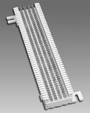
The 66-block was the most common of the punch-down blocks. It was used with telephone cabling for many years, but is not used in modern structured wiring installations. A number of different types of 66-blocks exist, but the most common is the 66M1-50 pictured in Figure 1.

 
Figure 1: A 66-block
The 66M1-50 has 50 horizontal rows of IDC connectors; each row consists of four prongs called bifurcated contact prongs. A side view of a row of contact prongs is shown in Figure 2. They are called bifurcated contact prongs because they are split in two pieces. The wire is inserted between one of the clips, and then the punch-down (impact) tool applies pressure to insert the wire between the two parts of the clip.

 
Figure 2: The 66-block contact prongs
The clips are labeled 1, 2, 3, and 4. The 66-block clips in Figure 2 show that the two clips on the left (clips 1 and 2) are electrically connected together, as are the two clips (clips 3 and 4) on the right. However, the two sets of clips are not electrically connected to one another. Wires can be terminated on both sides of the 66-block, and a metal "bridging" clip is inserted between clips 1 and 2 and clips 3 and 4. This bridging clip mechanically and electrically joins the two sides together. The advantage to this is that the sides can be disconnected easily if you need to troubleshoot a problem.
Note 
Some 66-blocks have a 50-pin Telco connector on one side of the 66-block.
Figure 3 shows a common use of the 66-block; in this diagram, the phone lines from the phone company are connected to one side of the block. The lines into the PBX are connected on the other side. When the company is ready to turn the phone service on, the bridge clips are inserted, which makes the connection.

 
Figure 3: A 66-block separating phone company lines from the phone system
Note 
The 66-blocks are typically designed for solid-conductor cable. Stranded-conductor cables will easily come loose from the IDC-style connectors. Stranded-conductor 66-blocks are available, however.
Figure 4 shows a 66-block in use for a voice system. In this picture, you can see that parts of the 66-block connectors have bridging clips connecting them. This block also has a door that can be closed to protect the front of the block and prevent the bridging clips from being knocked off.

Photo courtesy of Computer Training Center

Figure 4: A 66-block used for voice applications
The most typical type of cable connected to a 66-block is the 25-pair cable. The wiring pattern used with the 66-block is shown in Figure 5. If you look at a 66-block, you will notice notches in the plastic clips on the left and right side. These notches indicate the beginning of the next binder group.

 
Figure 5: The 66-block wire color/pin assignments for 25-pair cables
Note 
The T568-A and T568-B wiring patterns do not apply to 66-blocks.
If you were to use 66-blocks and four-pair UTP cables instead of 25-pair cables, then the wire color/pin assignments would be as shown in Figure 6.

 
Figure 6: The 66-block wire color/pin assignments for four-pair cables