Sunday, December 18, 2011

Advantages of Fiber-Optic Cabling


The following advantages of fiber over other cabling systems explain why fiber is becoming the preferred network cabling medium for high-bandwidth, long-distance applications:
  • Immunity to electromagnetic interference (EMI)
  • Higher data rates
  • Longer maximum distances
  • Better security

Immunity to Electromagnetic Interference (EMI)

All copper-cable network media share one common problem: they are susceptible to EMI. EMI is stray electromagnetism that interferes with electrical data transmission. All electrical cables generate a magnetic field around their central axis. If you pass a metal conductor through a magnetic field, an electrical current is generated in that conductor.
When you place two copper communication cables next to each other, EMI will cause crosstalk; signals from one cable will be picked up on the other. The longer a particular copper cable is, the more chance for crosstalk.
Fiber-optic cabling is immune to crosstalk because optical fiber does not conduct electricity and uses light signals in a glass fiber, rather than electrical signals along a metallic conductor, to transmit data. So it cannot produce a magnetic field and thus is immune to EMI. Fiber-optic cables can therefore be run in areas considered to be "hostile" to regular copper cabling (such as elevator shafts, electrical transformers, in tight bundles with other electrical cables, and industrial machinery).

Higher Possible Data Rates

Because light is immune to interference, can be modulated at very high frequencies, and travels almost instantaneously to its destination, much higher data rates are possible with fiber-optic cabling technologies than with traditional copper systems. Data rates far exceeding the gigabit per second (Gbps) range and higher are possible, and the latest IEEE standards body is working on 100Gbps fiber-based applications over much longer distances than copper cabling. Multimode is the preferred fiber-optic type for 100–550 meters seen in LAN networks, and since single-mode fiber-optic cables are capable of transmitting at these multi-gigabit data rates over very long distances, they are the preferred media for transcontinental and oceanic applications.
You will often encounter the word "bandwidth" when describing fiber-optic data rates. With optical fiber, bandwidth does not refer to channels or frequency, but rather just the bit-throughput rate.

Longer Maximum Distances

Typical copper data-transmission media are subject to distance limitations of maximum segment lengths no longer than 100 meters. Because they don't suffer from the EMI problems of traditional copper cabling and because they don't use electrical signals that can degrade substantially over long distances, single-mode fiber-optic cables can span distances up to 75 kilometers (about 46.6 miles) without using signal-boosting repeaters.

Better Security

Copper-cable transmission media are susceptible to eavesdropping through taps. A tap (short for wiretap) is a device that punctures through the outer jacket of a copper cable and touches the inner conductor. The tap intercepts signals sent on a LAN and sends them to another (unwanted) location. Electromagnetic (EM) taps are similar devices, but rather than puncturing the cable, they use the cable's magnetic fields, which are similar to the pattern of electrical signals. If you'll remember, simply placing a conductor next to a copper conductor with an electrical signal in it will produce a duplicate (albeit lower-power) version of the same signal. The EM tap then simply amplifies that signal and sends it on to the person who initiated the tap.
Because fiber-optic cabling uses light instead of electrical signals, it is immune to most types of eavesdropping. Traditional taps won't work because any intrusion on the cable will cause the light to be blocked and the connection simply won't function. EM taps won't work because no magnetic field is generated. Because of its immunity to traditional eavesdropping tactics, fiber-optic cabling is used in networks that must remain secure, such as government and research networks.

Wednesday, December 14, 2011

Introducing Fiber-Optic Transmission


Fiber-optic technology is different in its operation than standard copper media because the transmissions are "digital" light pulses instead of electrical voltage transitions. Very simply, fiber-optic transmissions encode the ones and zeroes of a digital network transmission by turning on and off the light pulses of a laser light source, of a given wavelength, at very high frequencies. The light source is usually either a laser or some kind of light-emitting diode (LED). The light from the light source is flashed on and off in the pattern of the data being encoded. The light travels inside the fiber until the light signal gets to its intended destination and is read by an optical detector, as shown in Figure 1.

 
Figure 1: Reflection of a light signal within a fiber-optic cable
Fiber-optic cables are optimized for one or more wavelengths of light. The wavelength of a particular light source is the length, measured in nanometers (billionths of a meter, abbreviated nm), between wave peaks in a typical light wave from that light source (as shown in Figure 2). You can think of a wavelength as the color of the light, and it is equal to the speed of light divided by the frequency. In the case of single-mode fiber, many different wavelengths of light can be transmitted over the same optical fiber at any one time. This is useful for increasing the transmission capacity of the fiber-optic cable since each wavelength of light is a distinct signal. Therefore, many signals can be carried over the same strand of optical fiber. This requires multiple lasers and detectors and is referred to as wavelength-division multiplexing (WDM).

 
Figure 2: A typical light wave
Typically, optical fibers use wavelengths between 850 and 1550nm, depending on the light source. Specifically, multimode fiber is used at 850 or 1300nm and single-mode fiber is typically used at 1310, 1490, and 1550nm (and, in WDM systems, in wavelengths around these primary wavelengths). The latest technology is extending this to 1625nm for single-mode fiber that is being used for next-generation passive optical networks (PON) for FTTH (fiber-to-the-home) applications. Silica-based glass is most transparent at these wavelengths, and therefore the transmission is more efficient (there is less attenuation of the signal) in this range. For a reference, visible light (the light that you can see) has wavelengths in the range between 400 and 700nm. Most fiber-optic light sources operate within the near infrared range (between 750 and 2500nm). You can't see infrared light, but it is a very effective fiber-optic light source.
Note 
Most traditional light sources can only operate within the visible wavelength spectrum and over a range of wavelengths, not at one specific wavelength. Lasers (light amplification by stimulated emission of radiation) and LEDs produce light in a more limited, even single-wavelength, spectrum.
Figure 3 shows the typical attenuation of single-mode and multimode fibers as a function of wavelength in this range. As you can see, the attenuation of these fibers is lower at longer wavelengths. As a result, longer distance communications tends to occur at 1310 and 1550nm wavelengths over single-mode fibers.

 
Figure 3: Attenuation of single-mode and multimode fibers
Notice that typical fibers have a larger attenuation at 1385nm. This water peak is a result of very small amounts (in the part-per-million range) of water incorporated during the manufacturing process. Specifically it is a terminal –OH (hydroxyl) molecule that happens to have its characteristic vibration at the 1385nm wavelength; thereby contributing to a high attenuation at this wavelength. Historically, communications systems operated on either side of this peak. However, in 1999 Lucent Technologies's optical fiber division (now OFS) created a zero water peak (ZWP) process whereby this water peak was eliminated by significantly reducing and then modifying the OH molecule.
To help you understand, let's use a very simple spring and weight analogy: If you replace the hydrogen with deuterium (an isotope of hydrogen that weighs twice as much) the molecule would now have a characteristic vibration that is not at a frequency of 1385nm and therefore does not cause high attenuation—still there, but out of the way. This invention opened up this wavelength range to transmission systems and allowed the International Telecommunication Union (ITU) to create a new operating band referred to as the E-band. This type of fiber is commonly referred to as low water peak (LWP) and has been standardized in the industry as ITU-T G.652D fiber. Earlier fibers had much larger attenuations at 1385nm and are referred to as ITU-T G.652B fiber.
Warning 
Laser light sources used with fiber-optic cables are extremely hazardous to your vision. Looking directly at the end of a live optical fiber can cause severe damage to your retinas. You could be made permanently blind. Never look at the end of a fiber-optic cable without first knowing that no light source is active.
When the light pulses reach the destination, a sensor picks up the presence or absence of the light signal and transforms the pulses of light back into electrical signals.
The more the light signal scatters or confronts boundaries, the greater the likelihood of signal loss (attenuation). Additionally, every fiber-optic connector between signal source and destination presents the possibility for signal loss. Thus, the connectors must be installed correctly at each connection.
Most LAN/WAN fiber transmission systems use one fiber for transmitting and one for reception. However, the latest technology allows a fiber-optic transmitter to transmit in two directions over the same fiber strand. The different wavelengths of light do not interfere with each other since the detectors are tuned to only read specific wavelengths. Therefore, the more wavelengths you send over a single strand of optical fiber, the more detectors you need.

Sunday, December 11, 2011

Common Problems with Copper Cabling


Sophisticated testers may provide a reason for a failed test. Some of the problems you may encounter include:
  • Length problems
  • Wire-map problems
  • NEXT and FEXT (crosstalk) problems
  • Attenuation problems

Length Problems

If a cable tester indicates that you have length problems, the most likely cause is that the cable you have installed exceeds the maximum length. Length problems may also occur if the cable has an open or short. Another possible problem is that the cable tester's NVP (Nominal Velocity of Propagation) setting is configured incorrectly. To correct it, run the tester's NVP diagnostics or setup to make sure that the NVP value is set properly. The NVP value can be obtained from the cable manufacturer if it's not properly installed in your tester.

Wire-Map Problems

When the cable tester indicates a wire-map problem, pairs are usually transposed in the wire. This is often a problem when mixing equipment that supports the T568-A and T568-B wiring patterns; it can also occur if the installer has split the pairs (individual wires are terminated on incorrect pins). A wire-map problem may also indicate an open or short in the cable.

NEXT and FEXT (Crosstalk) Problems

If the cable tester indicates crosstalk problems, the signal in one pair of wires is "bleeding" over into another pair of wires; when the crosstalk values are strong enough, this can interfere with data transmission. NEXT problems indicate that the cable tester has measured too much crosstalk on the near end of the connection. FEXT problems indicate too much crosstalk on the opposite side of the cable. Crosstalk is often caused by the conductors of a pair being separated, or "split," too much when they are terminated. Crosstalk problems can also be caused by external interference from EMI sources and cable damage or when components (patch panels and connectors) that are only supported for lower categories of cabling are used.
NEXT failures reported on very short cable runs, 15 meters (50) and less, require special consideration. Such failures are a function of signal harmonics, resulting from imbalance in either the cable or the connecting hardware or induced by poor-quality installation techniques. The hardware or installation (punch-down) technique is usually the culprit, and you can fix the problem by either re-terminating (taking care not to untwist the pairs) or by replacing the connecting hardware with a product that is better electrically balanced. It should be noted that most quality NICs are constructed to ignore the "short-link" phenomenon and may function just fine under these conditions.

Attenuation Problems

When the cable tester reports attenuation problems, the cable is losing too much signal across its length. This can be a result of the cabling being too long. Also check to make sure the cable is terminated properly. When running horizontal cable, make sure that you use solid-conductor cable; stranded cable has higher attenuation than solid cable and can contribute to attenuation problems over longer lengths. Other causes of attenuation problems include high temperatures, cable damage (stretching the conductors), and the wrong category of components (patch panels and connectors).

Thursday, December 8, 2011

Testing Copper Cable Media


Every cable run must receive a minimum level of testing. You can purchase $5,000 cable testers that will provide you with many statistics on performance, but the most important test is simply determining that the pairs are connected properly.
The $5,000 testers provide you with much more performance data than the simple cable testers and will also certify that each cable run will operate at a specific performance level. Some customers will insist on viewing results on the $5,000 cable tester, but the minimum tests you should run will determine continuity and ascertain that the wire map is correct. You can perform a couple of levels of testing. The cable testers that you can use include the following:
  • Tone generators and amplifier probes
  • Continuity testers
  • Wire-map testers
  • Cable-certification testers

Tone Generators and Amplifier Probes

If you have a bundle of cable and you need to locate a single cable within the bundle, using a tone generator and amplifier is the answer. Often, cable installers will pull more than one cable (sometimes dozens) to a single location, but they will not document the ends of the cables. The tone generator is used to send an electrical signal through the cable. On the other side of the cable, the amplifier (a.k.a. the inductive amplifier) is placed near each cable until a sound from the amplifier is heard, indicating that the cable is found. Figure 1 shows a tone generator and amplifier probe from IDEAL DataComm.


Figure 1: A tone generator and amplifier probe

Continuity Testing

The simplest test you can perform on a cable is the continuity test. It ensures that electrical signals are traveling from the point of origin to the receiving side. Simple continuity testers only guarantee that a signal is being received; they do not test attenuation or crosstalk.

Wire-Map Testers

A wire-map tester is capable of examining the pairs of wires and indicating whether or not they are connected correctly through the link. These testers will also indicate if the continuity of each wire is good. As long as good installation techniques are used and the correct category of cables, connectors, and patch panels are used, many of the problems with cabling can be solved by a simple wire-map tester. Figure 2 shows a simple tester from IDEAL DataComm that performs both wire-map testing and continuity testing.


Figure 2: A simple cable-testing tool

Cable Certification

If you are a professional cable installer, you may be required to certify that the cabling system you have installed will perform at the required levels. Testing tools more sophisticated than a simple continuity tester or wire-map tester perform these tests. The tools have two components, one for each side of the cable link. Tools such as the DTX CableAnalyzer Series from Fluke perform, analyze, and document many sophisticated tests that the less expensive scanners cannot.

Sunday, December 4, 2011

Sample Voice Installations


In many ways, voice installations are quite similar to data installations. The differences are the type of equipment that each end of the link is plugged into and, sometimes, the type of patch cables used. The ANSI/TIA-568-C standard requires at least one four-pair, unshielded twisted-pair cable to be run to each workstation outlet installed. This cable is to be used for voice applications. We recommend using a minimum of Category 3 cable for voice applications; however, if you will purchase Category 5e or higher cable for data, we advise using the same category of cable for voice. This potentially doubles the number of outlets that can be used for data.
Some sample cabling installations follow; we have seen them installed to support voice and data. Because so many possible combinations exist, we will only be able to show you a few. The first one (shown in Figure 1) is common in small- to medium-sized installations. In this example, each horizontal cable designated for voice terminates to an RJ-45 patch panel. A second patch panel has RJ-45 blocks terminated to the extensions on the phone switch or PBX. This makes moving a phone extension from one location to another as simple as moving the patch cable. If this type of flexibility is required, this configuration is an excellent choice.

 
Figure 1: A voice application using RJ-45 patch panels
Tip 
Any wiring system that terminates horizontal wiring into an RJ-45-type patch panel will be more versatile than traditional cross-connect blocks because any given wall-plate port/patch-panel port combination can be used for either voice or data. However, cabling professionals generally recommend separate patch panels for voice and data. Separate panels prevent interference that might occur as a result of incompatible systems and different frequencies used on the same patch panels.
The next example illustrates a more complex wiring environment, which includes backbone cabling for the voice applications. This example could employ patch panels in the telecommunications closet or 66-blocks, depending on the flexibility desired. The telecommunications closet is connected to the equipment room via twisted-pair backbone cabling. Figure 2 illustrates the use of patch panels, 66-blocks, and backbone cabling.

 
Figure 2: A voice application with a voice backbone, patch panels, and 66-blocks
The final example is the most common for voice installations; it uses 66-blocks exclusively. You will find many legacy installations that have not been modernized to use 110-block connections. Note that in Figure 3 two 66-blocks are connected by cross-connected cable. Cross-connect cable is simple single-pair, twisted-pair wire that has no jacket. You can purchase cross-connect wire, so don't worry about stripping a bunch of existing cables to get it. The example shown in Figure 3 is not as versatile as it would be if you used patch panels because 66-blocks require either reconnecting the cross-connect or reprogramming the PBX.

 
Figure 3: Voice applications using 66-blocks exclusively
Figure 4 shows a 66-block with cross-connect wires connected to it. Though you cannot tell it from the figure, cross-connect wires are often red and white.


Figure 4: A 66-block with cross-connect wires
The examples of 66-blocks and 110-blocks in this chapter are fairly common, but we could not possibly cover every possible permutation and usage of these types of blocks. We hope we have given you a representative view of some possible configurations.

Tuesday, November 29, 2011

66-Blocks | Copper Cable for Voice Applications


The 66-block was the most common of the punch-down blocks. It was used with telephone cabling for many years, but is not used in modern structured wiring installations. A number of different types of 66-blocks exist, but the most common is the 66M1-50 pictured in Figure 1.

 
Figure 1: A 66-block
The 66M1-50 has 50 horizontal rows of IDC connectors; each row consists of four prongs called bifurcated contact prongs. A side view of a row of contact prongs is shown in Figure 2. They are called bifurcated contact prongs because they are split in two pieces. The wire is inserted between one of the clips, and then the punch-down (impact) tool applies pressure to insert the wire between the two parts of the clip.

 
Figure 2: The 66-block contact prongs
The clips are labeled 1, 2, 3, and 4. The 66-block clips in Figure 2 show that the two clips on the left (clips 1 and 2) are electrically connected together, as are the two clips (clips 3 and 4) on the right. However, the two sets of clips are not electrically connected to one another. Wires can be terminated on both sides of the 66-block, and a metal "bridging" clip is inserted between clips 1 and 2 and clips 3 and 4. This bridging clip mechanically and electrically joins the two sides together. The advantage to this is that the sides can be disconnected easily if you need to troubleshoot a problem.
Note 
Some 66-blocks have a 50-pin Telco connector on one side of the 66-block.
Figure 3 shows a common use of the 66-block; in this diagram, the phone lines from the phone company are connected to one side of the block. The lines into the PBX are connected on the other side. When the company is ready to turn the phone service on, the bridge clips are inserted, which makes the connection.

 
Figure 3: A 66-block separating phone company lines from the phone system
Note 
The 66-blocks are typically designed for solid-conductor cable. Stranded-conductor cables will easily come loose from the IDC-style connectors. Stranded-conductor 66-blocks are available, however.
Figure 4 shows a 66-block in use for a voice system. In this picture, you can see that parts of the 66-block connectors have bridging clips connecting them. This block also has a door that can be closed to protect the front of the block and prevent the bridging clips from being knocked off.

Photo courtesy of Computer Training Center

Figure 4: A 66-block used for voice applications
The most typical type of cable connected to a 66-block is the 25-pair cable. The wiring pattern used with the 66-block is shown in Figure 5. If you look at a 66-block, you will notice notches in the plastic clips on the left and right side. These notches indicate the beginning of the next binder group.

 
Figure 5: The 66-block wire color/pin assignments for 25-pair cables
Note 
The T568-A and T568-B wiring patterns do not apply to 66-blocks.
If you were to use 66-blocks and four-pair UTP cables instead of 25-pair cables, then the wire color/pin assignments would be as shown in Figure 6.

 
Figure 6: The 66-block wire color/pin assignments for four-pair cables

Tuesday, November 15, 2011

Sample Data Installations


As long as you follow the ANSI/TIA-568-C standard, most of your communications infrastructure will be pretty similar and will not vary based on whether it is supporting voice or a specific data application. The horizontal cables will all follow the same structure and rules. However, when you start using the cabling for data applications, you'll notice some differences. We will now take a look at a couple of possible scenarios for using a structured cabling system.
The first scenario, shown in Figure 1, shows the typical horizontal cabling terminated to a patch panel. The horizontal cable terminates to the 110-block on the back of the patch panel. When a workstation is connected to the network, it is connected to the network hub by means of a RJ-45 patch cable that connects the appropriate port on the patch panel to a port on the hub.

 
Figure 1: A structured cabling system designed for use with data
The use of a generic patch panel in Figure 2 allows this cabling system to be the most versatile and expandable. Further, the system can also be used for voice applications if the voice system is also terminated to patch panels.
Another scenario involves the use of 110-blocks with 50-pin Telco connectors. These 50-pin Telco connectors are used to connect to phone systems or to hubs that are equipped with the appropriate 50-pin Telco interface. These are less versatile than patch panels because each connection must be terminated directly to a connection that connects to a hub.
In past years, we have worked with these types of connections, and network administrators have reported to us that these are more difficult to work with. Further, these 50-pin Telco connectors may not be interchangeable with equipment you purchase in the future. Figure 3 shows the use of a 110-block connecting to network equipment using a 50-pin Telco connector.

 
Figure 2: A structured cabling system terminated into 110-connecting blocks with 50-pin Telco connectors
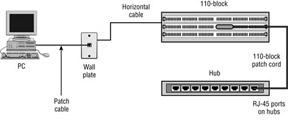
A final scenario that is a combination of the patch-panel approach and the 110-block approach is the use of a 110-block and 110-block patch cables. This is almost identical to the patch-panel approach, except that the patch cables used in the telecommunications closet have a 110-block connector on one side and an RJ-45 on the other. This configuration is shown in Figure 3.
Image from book 
Figure 3: Structured cabling using 110-blocks and 110-block patch cords
The previous examples are fairly simple and involve only one wiring closet. Any installation that requires more than one telecommunications closet and also one equipment room will require the service of a data backbone. Figure 4 shows an example where data backbone cabling is required. Due to distance limitations on horizontal cable when it is handling data applications, all horizontal cable is terminated to network equipment (hubs) in the telecommunications closet. The hub is then linked to other hubs via the data backbone cable.

 
Figure 4: Structured cabling that includes data backbone cabling

Friday, November 11, 2011

110-Blocks | Copper Cable for Data Applications


The telecommunications industry used the 66-style block for many years, and it was considered the mainstay of the industry. The 66-blocks were traditionally used only for voice applications; though we have seen them used to cross-connect data circuits, this is not recommended. The 110-blocks are newer than 66-blocks and have been designed to overcome some of the problems associated with 66-blocks. The 110-blocks were designed to support higher-frequency applications, accommodate higher-density wiring arrangements, and better separate the input and output wires.

The standard 66-block enabled you to connect 25 pairs of wires to it, but the 110-blocks are available in many different configurations supporting not only 25 pairs of wire but 50, 100, 200, and 300 pairs of wires as well. The 110-block has two primary components: the 110 wiring block on which the wires are placed, and the 110-connecting block (shown in Figure 1), which is used to terminate the wires. A 110-wiring block will consist of multiple 110-connector blocks; there will be one 110-connector block for each four-pair cable that must be terminated.

 
Figure 1: The 110-connector block
The 110-wiring block will consist of a few or many rows of 110-connector blocks. The wires are inserted into the connecting block and terminated by a punch-down tool or vendor-specific tool. These blocks are a type of IDC (insulation displacement connector); as the wires make contact with the metal on the blocks, the insulation is sliced, and the metal makes contact with the conductor. Remember, to prevent excessive crosstalk, don't untwist the pairs more than 0.5 inches for Category 5e, and 0.375 inches for Category 6 cable, when terminating onto a 110-connecting block.
The 110-blocks come in a wide variety of configurations. Some simply allow the connection of 110-block jumper cables. Figure 2 shows a 110-block jumper cable; one side of the cable is connected to the 110-block, and the other side is a modular eight-pin plug (RJ-45).


Photo courtesy of The Siemon Company

Figure 2: A 110-block to RJ-45 patch cable
Other 110-blocks have RJ-45 connectors adjacent to the 110-blocks, such as the one shown in Figure 3. If the application uses the 50-pin Telco connectors such as some Ethernet equipment and many voice applications do, 110-blocks such as the one shown in Figure 4 can be purchased that terminate cables to the 110-connecting blocks but then connect to 50-pin Telco connectors.

Photo courtesy of The Siemon Company

Figure 3: A 110-block with RJ-45 connectors on the front

Photo courtesy of The Siemon Company

Figure 4: A 110-block with 50-pin Telco connectors
You will also find 110-blocks on the back of patch panels; each 110-connecting block has a corresponding port on the patch panel. Figure 5 shows the 110-block on the back of a patch panel. The front side of the patch panel shown in Figure 6 shows a 96-port patch panel; each port will have a corresponding 110-connecting block.


Photo courtesy of Computer Training Academy

Figure 4: A 110-block on the back side of a patch panel


Photo courtesy of MilesTek

Figure 5: A 96-port patch panel