As long as you follow the ANSI/TIA-568-C standard, most of your communications infrastructure will be pretty similar and will not vary based on whether it is supporting voice or a specific data application. The horizontal cables will all follow the same structure and rules. However, when you start using the cabling for data applications, you'll notice some differences. We will now take a look at a couple of possible scenarios for using a structured cabling system.
The first scenario, shown in Figure 1, shows the typical horizontal cabling terminated to a patch panel. The horizontal cable terminates to the 110-block on the back of the patch panel. When a workstation is connected to the network, it is connected to the network hub by means of a RJ-45 patch cable that connects the appropriate port on the patch panel to a port on the hub.
The use of a generic patch panel in Figure 2 allows this cabling system to be the most versatile and expandable. Further, the system can also be used for voice applications if the voice system is also terminated to patch panels.
Another scenario involves the use of 110-blocks with 50-pin Telco connectors. These 50-pin Telco connectors are used to connect to phone systems or to hubs that are equipped with the appropriate 50-pin Telco interface. These are less versatile than patch panels because each connection must be terminated directly to a connection that connects to a hub.
In past years, we have worked with these types of connections, and network administrators have reported to us that these are more difficult to work with. Further, these 50-pin Telco connectors may not be interchangeable with equipment you purchase in the future. Figure 3 shows the use of a 110-block connecting to network equipment using a 50-pin Telco connector.
Figure 2: A structured cabling system terminated into 110-connecting blocks with 50-pin Telco connectors
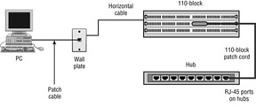
A final scenario that is a combination of the patch-panel approach and the 110-block approach is the use of a 110-block and 110-block patch cables. This is almost identical to the patch-panel approach, except that the patch cables used in the telecommunications closet have a 110-block connector on one side and an RJ-45 on the other. This configuration is shown in Figure 3.
The previous examples are fairly simple and involve only one wiring closet. Any installation that requires more than one telecommunications closet and also one equipment room will require the service of a data backbone. Figure 4 shows an example where data backbone cabling is required. Due to distance limitations on horizontal cable when it is handling data applications, all horizontal cable is terminated to network equipment (hubs) in the telecommunications closet. The hub is then linked to other hubs via the data backbone cable.


great post , thank u for your blog visit us fiber optic solutions in dubai
ReplyDelete