When you start installing copper cabling, much can go wrong. Even if you have adequately planned your installation, situations can still arise that will cause you problems either immediately or in the long term. Here are some tips to keep in mind for installing copper cabling:
Do not untwist the twisted pairs at the cable connector or anywhere along the cable length any more than necessary (less than 0.5″ for Category 5e, and less than 0.375″ for Category 6).
Taps (bridged taps) are not allowed.
Use connectors, patch panels, and wall plates that are compatible with the cable.
When tie-wrapping cables, do not overtighten cable bundles. Instead of tie-wraps, use Velcro® type wraps. While they are more expensive, they are easily reused if the cables require rearrangement.
Staples are not recommended for fastening cables to supports.
Never splice a data cable if it has a problem at some point through its length; run a new cable instead.
When terminating, remove as little of the cable's jacket as possible, preferably less than three inches. When finally terminated, the jacket should be as close as possible to where the conductors are punched down.
Don't lay data cables directly across ceiling tiles or grids. Use a cable tray, J hook, horizontal ladder, or other method to support the cables. Avoid any sort of cable-suspension device that appears as if it will crush the cables.
Follow proper grounding procedures for all equipment to reduce the likelihood of electrical shock and reduce the effects of EMI.
All voice runs should be home-run, not daisy-chained. When wiring jacks for home or small office telephone use, the great temptation is to daisy-chain cables together from one jack to the next. Don't do it. For one thing, it won't work with modern PBX (private branch exchange) systems. For another, each connection along the way causes attenuation and crosstalk, which can degrade the signal even at voice frequencies.
If you have a cable with damaged pairs, replace it. You will be glad you did. Don't use another unused pair from the same cable because other pairs may be damaged to the point where they only cause intermittent problems, which are difficult to solve. Substituting pairs also prevents any future upgrades that require the use of all four pairs in the cable.
Pulling Cable
If you are just starting out in the cabling business or if you have never been around cable when it is installed, the term
pulling cable is probably not significant. However, any veteran installer will tell you that
pulling is exactly what you do. Cable is pulled from boxes or spools, passed up into the ceiling, and then, every few feet, the installers climb into the ceiling and pull the cable along a few more feet. In the case of cable in conduit, the cable is attached to a drawstring and pulled through.
While the cable is pulled, a number of circumstances can happen that will cause irreparable harm to the cable. But you can take steps to make sure that damage is avoided. Here is a list of copper-cabling installation tips:
Do not exceed the cable's minimum bend radius by making sharp bends. The bend radius for four-pair UTP cables should not be less than four times the cable diameter and not less than 10 times the cable diameter for multi-pair (25-pair and greater cable). Avoid making too many 90-degree bends.
Do not exceed maximum cable pulling tension (110N or 25 pounds of force for four-pair UTP cable).
When pulling a bundle of cables, do not pull cables unevenly. It is important that all the cables share the pulling tension equally.
When building a system that supports both voice and data, run the intended voice lines to a patch panel separate from the data lines.
Be careful not to twist the cable too tightly; doing so can damage the conductors and the conductor insulation.
Avoid pulling the cable past sources of heat such as hot-water pipes, steam pipes, or warm-air ducts.
Be aware that damage can be caused by all sorts of other evil entities such as drywall screws, wiring-box edges, and other sharp objects found in ceilings and walls.
New cable is shipped in reels or coils. Often the reels are in boxes and the cable easily unspools from the boxes as you pull on it. Other times, the cable reels are not in a box, and you must use some type of device to allow the reel to turn freely while you pull the cable. In these cases, a device similar to the one pictured in Figure 1 may be just the ticket. These are often called wire-spool trees. For emergency or temporary use, a broomstick or piece of conduit through a stepladder will work.
When the coils are inside a box, you dispense the cable directly from the box by pulling on it. You should never take these coils from the box and try to use them. The package is a special design and without the box the cable will tangle hopelessly.
| Tip |
When troubleshooting any wiring system, disconnect the data or voice application from both sides (the phone, PC, hub, and PBX). This goes for home telephone wiring, too!
|
Separating Voice and Data Patch Panels
Some installations of voice and data cabling will terminate the cabling on the same patch panel. Although this is not entirely frowned upon by cabling professionals, many will tell you that it is more desirable to have a separate patch panel dedicated to voice applications. This is essential if you use a different category of cable for voice than for data (such as if you use Category 5e cable for data but Category 3 cable for voice).
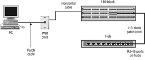
In the example in Figure 2, the wall plate has two eight-position modular outlets (one for voice and one for data). The outlets are labeled V1 for voice and D1 for data. In the telecommunications closet, these two cables terminate on different patch panels, but each cable goes to position 1 on the patch panel. This makes the cabling installation much easier to document and to understand. The assumption in Figure 2 is that the voice system is terminating to a patch panel rather than a 66-block. The voice system is then patched to another patch panel that has the extensions from the company's PBX, and the data port is patched to a network hub.
Sheath Sharing
The ANSI/TIA-568-C standard does not specifically prohibit sheath sharing—that is, when two applications share the same sheath—but its acknowledgment of this practice is reserved for cables with more than four pairs. Occasionally, though, someone may decide that he or she cannot afford to run two separate four-pair cables to a single location and may use different pairs of the cable for different applications. Table 7.5 shows the pin arrangement that might be used if a splitter were employed. Some installations may split the cable at the wall outlet and patch panel rather than using a splitter.
Table 1: Shared-Sheath Pin Assignments
Pin Number
|
Usage
|
T568-A Wire Color
|
T568-B Wire Color
|
|---|
Pin 1
|
Ethernet transmit +
|
White/green
|
White/orange
|
Pin 2
|
Ethernet transmit –
|
Green
|
Orange
|
Pin 3
|
Ethernet receive +
|
White/orange
|
White/green
|
Pin 4
|
Phone inner wire 1
|
Blue
|
Blue
|
Pin 5
|
Phone inner wire 2
|
White/blue
|
White/blue
|
Pin 6
|
Ethernet receive −
|
Orange
|
Green
|
Pin 7
|
Phone inner wire 3
|
White/brown
|
White/brown
|
Pin 8
|
Phone inner wire 4
|
Brown
|
Brown
|
When two applications share the same cable sheath, performance problems can occur. Two applications (voice and data or data and data) running inside the same sheath may interfere with one another. Applications operating at lower frequencies such as 10Base-T may work perfectly well, but higher-frequency applications such as 100Base-TX will operate with unpredictable results. Also, as previously noted, two applications sharing the same four-pair cable sheath will prevent future upgrades to faster LAN technologies such as Gigabit Ethernet.
Because results can be unpredictable, and because you probably want to future-proof your installation, we strongly recommend that you never use a single four-pair cable for multiple applications. Even for home applications where you may want to share voice and data applications (such as Ethernet and your phone service), we recommend separate cables. The ringer voltage on a home telephone can disrupt data transmission on adjacent pairs of wire, and induced voltage could damage your network electronics.
Avoiding Electromagnetic Interference
All electrical devices generate electromagnetic fields in the radio frequency (RF) spectrum. These electromagnetic fields produce EMI and interfere with the operation of other electric
devices and the transmission of voice and data. You will notice EMI if you have a cordless or cell phone and you walk near a microwave oven or other source of high EMI.
Data transmission is especially susceptible to disruption from EMI, so it is essential that cabling installed with the intent of supporting data (or voice) transmissions be separated from EMI sources. Here are some tips that may be helpful when planning pathways for data and voice cabling:
Data cabling must never be installed in the same conduit with power cables. Aside from the EMI issue, it is not allowed by the NEC.
If data cables must cross power cables, they should do so at right angles.
Power and data cables should never share holes bored through concrete, wood, or steel. Again, it is an NEC violation as well as an EMI concern.
Telecommunication outlets should be placed at the same height from the floor as power outlets, but they should not share stud space.
Maintain at least 2″ of separation from open electrical cables up to 300 volts. Six inches is a preferred minimum separation.
Maintain at least 6″ of separation from lighting sources or fluorescent-light power supplies.
Maintain at least 4″ of separation from antenna leads and ground wires.
Maintain at least 6″ of separation from neon signs and transformers.
Maintain at least 6′ of separation from lightning rods and wires.
Other sources of EMI include photocopiers, microwave ovens, laser printers, electrical motors, elevator shafts, generators, fans, air conditioners, and heaters.