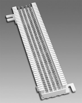
The 66-block was the most common of the punch-down blocks. It was used with telephone cabling for many years, but is not used in modern structured wiring installations. A number of different types of 66-blocks exist, but the most common is the 66M1-50 pictured in Figure 1.
The 66M1-50 has 50 horizontal rows of IDC connectors; each row consists of four prongs called bifurcated contact prongs. A side view of a row of contact prongs is shown in Figure 2. They are called bifurcated contact prongs because they are split in two pieces. The wire is inserted between one of the clips, and then the punch-down (impact) tool applies pressure to insert the wire between the two parts of the clip.

The clips are labeled 1, 2, 3, and 4. The 66-block clips in Figure 2 show that the two clips on the left (clips 1 and 2) are electrically connected together, as are the two clips (clips 3 and 4) on the right. However, the two sets of clips are not electrically connected to one another. Wires can be terminated on both sides of the 66-block, and a metal "bridging" clip is inserted between clips 1 and 2 and clips 3 and 4. This bridging clip mechanically and electrically joins the two sides together. The advantage to this is that the sides can be disconnected easily if you need to troubleshoot a problem.
| Note |
Some 66-blocks have a 50-pin Telco connector on one side of the 66-block.
|
Figure 3 shows a common use of the 66-block; in this diagram, the phone lines from the phone company are connected to one side of the block. The lines into the PBX are connected on the other side. When the company is ready to turn the phone service on, the bridge clips are inserted, which makes the connection.

| Note |
Figure 4 shows a 66-block in use for a voice system. In this picture, you can see that parts of the 66-block connectors have bridging clips connecting them. This block also has a door that can be closed to protect the front of the block and prevent the bridging clips from being knocked off.

The most typical type of cable connected to a 66-block is the 25-pair cable. The wiring pattern used with the 66-block is shown in Figure 5. If you look at a 66-block, you will notice notches in the plastic clips on the left and right side. These notches indicate the beginning of the next binder group.

| Note |
The T568-A and T568-B wiring patterns do not apply to 66-blocks.
|
If you were to use 66-blocks and four-pair UTP cables instead of 25-pair cables, then the wire color/pin assignments would be as shown in Figure 6.

Hi there. Nice blog. You have shared useful information. Keep up the good work! This blog is really interesting and gives good details. Switchgears, copper wire.
ReplyDeleteNice blog. vehicle tracking software provider in pune
ReplyDeletegreat post , thank u for your blog visit us fiber optic solutions in dubai
ReplyDelete