Monday, August 29, 2011

Cabling Racks and Enclosures

Racks are the pieces of hardware that help you organize cabling infrastructure. They range in height from 39 to 84 and come in two widths: 19 and 23. Nineteen-inch widths are much more commonplace and have been in use for nearly 60 years. These racks are commonly called just 19 racks or, sometimes, EIA racks. Mounting holes are spaced between ⅝″ and 2 apart, so you can be assured that no matter what your preferred equipment vendor is, its equipment will fit in your rack. In general, three types of racks are available for purchase: wall-mounted brackets, skeletal frames, and full equipment cabinets.
Tip 
Not all racks use exactly the same type of mounting screws or mounting equipment. Make sure that you have sufficient screws or mounting gear for the types of racks you purchase.

Wall-Mounted Brackets

For small installations and areas where economy of space is a key consideration, wall-mounted brackets may provide the best solution. Wall-mounted racks such as MilesTek's Swing Gate wall rack in Figure 1 have a frame that swings out 90 degrees to provide access to the rear panels and includes wire guides to help with cable management.
 
Figure 1: MilesTek's Swing Gate wall rack
Racks such as the one in Figure 1 are ideal for small organizations that may only have a few dozen workstations or phone outlets but are still concerned about building an organized cabling infrastructure.
Tip 
Prior to installing wall-mounted racks with swinging doors, be sure to allow enough room to open the front panel.

Skeletal Frames (19 Racks)

Skeletal frames, often called 19 racks or EIA racks, are probably the most common type of rack. These racks, like the one shown in Figure 2, are designed and built based on the EIA/ECA-310-E standard, issued in 2005. These skeletal frames come in sizes ranging from 39 to 84 in height with a 22 base plate to provide stability. Their open design makes it easy to work on both the front and back of the mounted equipment.
 
Figure 2: A skeletal frame (19 rack)
When installing a skeletal frame, you should leave enough space between the rack and the wall to accommodate the installed equipment (most equipment is 6 to 18 deep). You should also leave enough space behind the rack for an individual to work (at least 12 to 18). You will also need to secure the rack to the floor so that it does not topple over.
These racks can also include cable management. If you have ever worked with a rack that has more than a few dozen patch cords connected to it with no cable management devices, then you understand just how messy skeletal racks can be. Figure 3 shows an Ortronics Mighty Mo II wall-mount rack that includes cable management.

 
Figure 3: The Ortronics Mighty Mo II wall-mount rack with cable management
Racks are not limited to just patch panels and network connectivity devices. Server computers, for example, can be installed into a rack-mountable chassis. Many accessories can be mounted into rack spaces, including utility shelves, monitor shelves, and keyboard shelves. Figure 4 shows some of the more common types of shelves available for 19 racks. If you have a need for some sort of shelf not commercially available, most machine shops are equipped to manufacture it.

 
Figure 4: Shelves available for 19 racks

Full Equipment Cabinets

The most expensive of your rack options, full equipment cabinets, offer the security benefits of locking cabinet doors. Full cabinets can be as simple as the ones shown in Figure 5, but they can also become quite elaborate, with Plexiglas doors and self-contained cooling systems. Racks such as the one in Figure 5 provide better physical security, cooling, and protection against electromagnetic interference than standard 19 rack frames. In some high-security environments, this type of rack is required for LAN equipment and servers.

 
Figure 5: A full equipment cabinet

Cable Management Accessories

If your rack equipment does not include wire management, numerous cable management accessories, as shown in Figure 6, can suit your organizational requirements. Large telecommunications rooms can quickly make a rat's nest out of your horizontal cable runs and patch cables. Cable hangers on the front of a rack can help arrange bundles of patch cables to keep them neat and orderly. Rear-mounted cable hangers provide strain-relief anchors and can help to organize horizontal cables that terminate at the back of patch panels.


Figure 6: Cable management accessories from MilesTek

Electrical Grounding

In our discussion on conduit, we stated that regardless of your conduit solution, you will have to make sure that it complies with the ANSI/TIA-607-B Commercial Building Grounding and Bonding Requirements for Telecommunications Standard for electrical grounding. The same holds true for your cable-rack implementations. Why is this so important? Well, to put it bluntly, your network can kill you, and in this case, we're not referring to the massive coronary brought on by users' printing challenges!
For both alternating- and direct-current systems, electrons flow from a negative to a positive source, with two conductors required to complete a circuit. If a difference in resistance exists between a copper wire path and a grounding path, a voltage potential will develop between your hardware and its earth ground. In the best-case scenario, this voltage potential will form a Galvanic cell, which will simply corrode your equipment. This phenomenon is usually demonstrated in freshman chemistry classes by using a potassium-chloride salt bridge to complete the circuit between a zinc anode and a copper cathode. If the voltage potential were to become great enough, however, simply touching your wiring rack could complete the circuit and discharge enough electricity to kill you or one of your colleagues.
Warning 
Grounding is serious business and should not be undertaken by the layperson. Low voltage does not mean large shocks cannot be generated.

We recommend working with your electrical contractor and power company to get the best and shortest ground you can afford. One way to achieve this is to deploy separate breaker boxes for each office area. Doing so will shorten the grounding length for each office or group.

Tuesday, August 23, 2011

TIA/EIA Recommendations for Telecommunications Rooms


The TIA/EIA does not distinguish between the roles of telecommunications rooms for its published standards. The following is a summary of the minimum standards for a telecommunications wiring room per the ANSI/TIA-569-B Commercial Building Telecommunications Pathways and Spaces Standard:
  • The telecommunications room must be dedicated to telecommunications functions.
  • Equipment not related to telecommunications shall not be installed in or enter the telecommunications room.
  • Multiple rooms on the same floor shall be interconnected by a minimum of one 78(3) (3 or 78mm opening) trade-size conduit or equivalent pathway.
  • The telecommunications room must support a minimum floor loading of 2.4 kilopascals (50 lbf/ft2).
The equipment room is used to contain the main distribution frame (the main location for backbone cabling), phone systems, power protection, uninterruptible power supplies, LAN equipment (such as bridges, routers, switches, and hubs), and any file servers and data processing equipment. TIA-569-B recommends a minimum of 0.75 square feet of floor space in the equipment room for every 100 square feet of user workstation area. You can also estimate the requirements for square footage using Table 1, which shows estimated equipment-room square footage based on the number of workstations.
Table 1: Estimated Square Foot Requirements Based on the Number of Workstations 
Number of Workstations
Estimated Equipment Room Floor Space
1 to 100
150 square feet
101 to 400
400 square feet
401 to 800
800 square feet
801 to 1,200
1,200 square feet


Note 
The floor space required in any equipment room will be dictated by the amount of equipment that must be housed there. Use Table 1 for a base calculation, but don't forget to take into account equipment that may be in this room, such as LAN racks, phone switches, and power supplies.
Here are some additional requirements:
  • There shall be a minimum of two dedicated 120V 20A nominal, nonswitched, AC duplex electrical-outlet receptacles, each on separate branch circuits.
  • Additional convenience duplex outlets shall be placed at 1.8 meter (6) intervals around the perimeter, 150mm (6) above the floor.
  • There shall be access to the telecommunications grounding system, as specified by ANSI/TIA-607-B.
  • HVAC requirements to maintain a temperature the same as the adjacent office area shall be met. A positive pressure shall be maintained with a minimum of one air change per hour or per code.
  • There shall be a minimum of one room per floor to house telecommunications equipment/cable terminations and associated cross-connect cable and wire.
  • The telecommunications room shall be located near the center of the area being served.
  • Horizontal pathways shall terminate in the telecommunications room on the same floor as the area served.
  • The telecommunications room shall accommodate seismic requirements.
  • Two walls should have 20mm (¾) A-C plywood 2.44m (8) high.
  • Lighting shall be a minimum of 500 lx (50 footcandles) and mounted 2.6m (8.5) above the floor.
  • False ceilings shall not be provided.
  • There shall be a minimum door size of 910mm (36) wide and 2,000mm (80) high without sill, hinged to open outward or slide side-to-side or be removable, and it shall be fitted with a lock.
Although these items are suggestions, we recommend that you strive to fulfill as many of these requirements as possible. If your budget only allows for a few of these suggestions, grounding, separate power, and the ventilation and cooling requirements should be at the top of your list.

Saturday, August 20, 2011

Telecommunications Rooms, Enclosures, and Equipment Rooms


The telecommunications room or enclosure is where your network devices are aggregated into switches. These switches route the signals from these devices to the equipment room where servers and storage equipment are located. In this section, we'll cover the function of these rooms, along with suggested design elements. From there, we'll discuss the pieces of equipment found within a typical telecommunications and equipment room. We'll conclude with a brief discussion on network devices.
Three types of wiring locations exist: telecommunications rooms, telecommunications enclosures, and equipment rooms.
Depending on the size of your organization and the size of your building, you may have one or more telecommunications rooms connecting into an equipment room. Telecommunications rooms are strategically placed throughout a building to provide a single point for termination from your work areas. In a multistory building, you should have at least one telecommunications room per floor. As the distances between your end devices and telecommunications room approach their recommended maximum limits (90 meters), you should consider implementing additional telecommunications rooms. Ideally, these are included during the planning stage prior to construction or remodeling.
Telecommunications rooms are connected to the equipment room in a star configuration by either fiber or copper backbone cables. As we mentioned in our discussion of backbone cabling, fiber is preferred because fiber allows for distances from the equipment room to the last telecommunications room of up to 2,000 meters for multimode and 3,000 meters for single mode. When connecting with UTP copper, the backbone run lengths must total no more than 800 meters for telephone systems and no more than 90 meters for data systems.
A telecommunications enclosure is essentially a mini-telecommunications room. These enclosures contain active switches and patch panels and have the same functionality as the equipment located in a telecommunications room. The advantage of using telecommunications enclosures instead of telecommunications rooms is in the higher switch port utilization and cost savings obtained from eliminating the construction of dedicated rooms and associated HVAC loading. The Fiber Optics LAN Section of TIA (www.fols.org) has conducted extensive cost modeling showing the advantages of using telecommunications enclosures. However, telecommunications enclosures do not come without disadvantages, such as the need to service certain types of telecommunications enclosures in an open workspace.

Wednesday, August 17, 2011

Cabling Pathways


We'll look at the cabling system components outlined by the TIA-569-B Commercial Building Telecommunications Pathways and Spaces Standard for concealing, protecting, and routing your cable plant. In particular, we'll describe the components used in work areas and telecommunications rooms and for horizontal and backbone cable runs. As you read these descriptions, you'll notice all components must be electrically grounded per the ANSI/TIA-607-B Commercial Building Grounding and Bonding Requirements for Telecommunications.

Conduit

Conduit is pipe. It can be metallic or nonmetallic, rigid or flexible (as permitted by the applicable electrical code), and it runs from a work area to a telecommunications room and a telecommunications room to an equipment room. One advantage of using conduit to hold your cables is that conduit may already exist in your building. Assuming the pipe has enough space, it shouldn't take long to pull your cables through it. A drawback to conduit is that it provides a finite amount of space to house cables. When drafting specifications for conduit, we recommend that you require that enough conduit be installed so that it would be only 40 percent full by your current cable needs. Conduit should be a maximum of 60 percent full. This margin leaves you with room for future growth.
According to the TIA-569-B standard, conduit can be used to route horizontal and backbone cables. Firestopped conduit can also be used to connect telecommunications rooms in multistoried buildings to an equipment room. Some local building codes require the use of conduit for all cable, both telecommunication and electrical.
In no cases should communication cables be installed in the same conduit as electrical cables without a physical barrier between them. Aside from (and because of) the obvious potential fire hazard, it is not allowed by the NEC.

Cable Trays

As an alternative to conduit, cable trays can be installed to route your cable. Cable trays are typically wire racks specially designed to support the weight of a cable infrastructure. They provide an ideal way to manage a large number of horizontal runs. Cables simply lie within the tray, so they are very accessible when it comes to maintenance and troubleshooting. The TIA-569-B standard provides for cable trays to be used for both horizontal and backbone cables.
Figure 1 shows a cable runway system. This type of runway looks like a ladder that is mounted horizontally inside the ceiling space or over the top of equipment racks in a telecommunications or equipment room. In the ceiling space, this type of runway keeps cables from being draped over the top of fluorescent lights, HVAC equipment, or ceiling tiles; the runway is also helpful in keeping cable from crossing electrical conduit. Separating the cable is especially useful near telecommunications and equipment rooms where there may be much horizontal cable coming together. When used in a telecommunications or equipment room, this runway can keep cables off the floor or can run from a rack of patch panels to an equipment rack.

 
Figure 1: A runway system used to suspend cables overhead
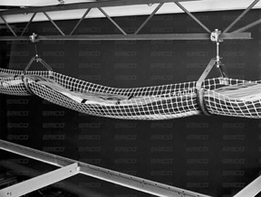
Another type of cable-suspension device is the CADDY CatTrax from ERICO. These cable trays are flexible and easy to install, and they can be installed in the ceiling space, telecommunications room, or equipment room. The CatTrax (shown in Figure 2) also keeps cables from being laid directly onto the ceiling tile of a false ceiling or across lights and electrical conduit because it provides continuous support for cables.

 
Figure 2: The CADDY CatTrax flexible cable tray from ERICO
Tip 
Numerous alternatives to cable-tray supports are available. One of the most common is a J hook. J hooks are metal supports in the shape of an L or J that attach to beams, columns, walls, or the structural ceiling. Cables are simply draped from hook to hook. Spacing of hooks should be from 4 to 5 maximum, and the intervals should vary slightly to avoid the creation of harmonic intervals that may affect transmission performance.

Raceways

Raceways are special types of conduits used for surface-mounting horizontal cables. Raceways are usually pieced together in a modular fashion with vendors providing connectors that do not exceed the minimum bend radius. Raceways are mounted on the outside of a wall in places where cable is not easily installed inside the wall; they are commonly used on walls made of brick or concrete where no telecommunications conduit has been installed. To provide for accessibility and modularity, raceways are manufactured in components (see Figure 3).

 
Figure 3: A surface-mounted modular raceway system
Figure 4 shows a sample of a surface-mount raceway carrying a couple of different cables; this raceway is hinged to allow cables to be easily installed.

 
Figure 4: A sample surface-mount raceway with cables
One-piece systems usually provide a flexible joint for opening the raceway to access cables; after opening, the raceway can be snapped shut. To meet information-output needs, raceway vendors often produce modular connectors to integrate with their raceway systems.

Fiber-Protection Systems

As with raceways, fiber-protection systems (see Figure 5) are special types of conduits and cable-management systems designed specifically to address the special protection needs of optical fiber cable. Although maintaining proper bend radius is important for all cable media, severe bends in optical fiber cable will result in attenuation and eventual signal loss, which translates to lost data, troubleshooting, downed network connections, and lost productivity. Severe bends can also lead to cracking and physical failure of the fiber. By employing rounded surfaces and corners, fiber-protection systems essentially limit the degree of bending put on an optical fiber cable. To protect your fiber investment, we recommend that you consider investing in a fiber-protection system.

 
Figure 5: The Siemon Company's LightWays fiber-protection system
KEY TERM: inner duct 
Inner duct is a flexible plastic conduit system often used inside a larger conduit; fiber-optic cable is run through it for an additional layer of protection.
When evaluating a prospective fiber-protection system, you should account for the total cost of the installation rather than just the cost of materials. Also ensure that it will support the weight of your cable without sagging. In addition, because your network will grow with time, you should consider how flexible the solution will be for future modifications. Will you be able to add new segments or vertical drops without having to move existing cable? The most expensive part of your system will be the labor costs associated with the installation. Does the system require special tools to install, or does it snap together in a modular fashion?